VGA Connections
VGA connections
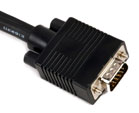
Nearly all modern PC graphics cards use the same 15 pin VGA connector that the original IBM VGA card used. VGA=Video Graphics adapter or Video Graphics Array. There are at least four versions of the VGA connector, which are the three-row 15 pin DE-15 (also called mini sub D15) in original and DDC2 pinouts, a less featureful and far less common 9-pin VGA, and a Mini-VGA used for laptops.
Whilst the graphics card and monitor may have 15 pins not all sytems use all 15 pins and not all VGA cables have enough wires to connect all the pins
The image and table below are the newer 15-pin VGA VESA DDC2 connector pinout used on modern monitors and projectors. This combination provides full DDC2AB control of the monitor or projector from the graphics card and connects all pins except pin 9 which is intentionally not connected, pins 5 and 10 are often common ie connected together.

|

|

|
| Pin | Name | Description | 15 Cores (5 Coax) connected | 9 cores (5 Coax) connected |
| 1 | RED | Red Video (75 ohm, 0.7 V p-p) | Red Coax | Red Coax |
| 2 | GREEN | Green Video (75 ohm, 0.7 V p-p) | Green Coax | Green Coax |
| 3 | BLUE | Blue Video (75 ohm, 0.7 V p-p) | Blue Coax | Blue Coax |
| 4 | ID2 | Monitor ID Bit 2 | Brown | |
| 5 | GND | Ground | Yellow drain (connected pin 10) | |
| 6 | RGND | Red Ground | Red drain | Red drain |
| 7 | GGND | Green Ground | Green drain | Green drain |
| 8 | BGND | Blue Ground | Blue drain | Blue drain |
| 9 | KEY | Key | Black | |
| 10 | SGND | Sync Ground | White drain (connected pin 5) | Black/Yellow drain |
| 11 | ID0 | Monitor ID Bit 0 | Red | |
| 12 | ID1 or SDA | Monitor ID Bit 1 | White | |
| 13 | HSYNC or CSYNC | Horizontal Sync (or Composite Sync) | White Coax | Black Coax |
| 14 | VSYNC | Vertical Sync | Yellow Coax | Yellow Coax |
| 15 | ID3 or SCL | Monitor ID Bit 3 | Grey or Blue | |
| Case/shell | Sheath drain | Sheath drain |
NOTE: There are 3 different protocols defined for DDC :
DDC1 - A unidirectional (display to host only) serial comm system which provides basic display ID and feature support information (including supported timings, display size, colorimetry and gamma, etc.) to the host. This uses pin 12 on the 15-pin "VGA" connector as a data line.
DDC2B - Adds clock (pin 15) and return (pin 11) to enable at least ID information to be obtained via an I2C interface. I2C is a bidirectional interface, but display control via DDC2B is not defined at this time.
DDC2AB - Full ID and control of the monitor via ACCESS.bus. As ACCESS.bus is basically a command and protocol definition on top of the I2C hardware interface, this uses the same lines as DDC2B.
There is no International colour standard for the Horizontal and Vertical Sync wires, so if cables other than Edisconnect cables are used the pin-outs should be checked using a tester to ensure the wires are connected to the correct pins.